
News

How to Choose Power Supply Connectors?

Choosing Power Supply Connectors is more than matching a plug to a socket. The connector must carry the required current safely and consistently. A small mismatch can create heat, voltage loss, or an intermittent connection.

Begin by checking voltage, current rating, wire size, pin spacing, and polarity. Then examine the connector’s locking method and mating cycles. A connector used inside industrial equipment may need stronger retention than one inside a quiet office device. Temperature, dust, moisture, vibration, and limited installation space also influence the choice. These details often decide whether a design remains reliable after months of operation.

Do not trust appearance alone. Two connectors may look identical but use different pin assignments or contact materials. Confirm the manufacturer’s datasheet, recommended wire range, insulation rating, and test conditions. Recognized certification can support a safer purchasing decision, but it does not replace application testing. Real assemblies should be checked under their actual load, cable movement, and operating temperature.

Small details matter.

In practical design reviews, engineers often discover that the cheapest connector creates higher labor costs later. A loose latch, difficult crimp, or fragile housing can slow maintenance. I have also seen specifications overlook future upgrades. That is an easy mistake. Rechecking the power budget and connector availability before production can prevent expensive redesigns. The best choice balances electrical performance, mechanical durability, sourcing stability, and the technician’s everyday experience. Expect some uncertainty, and verify critical assumptions before committing.
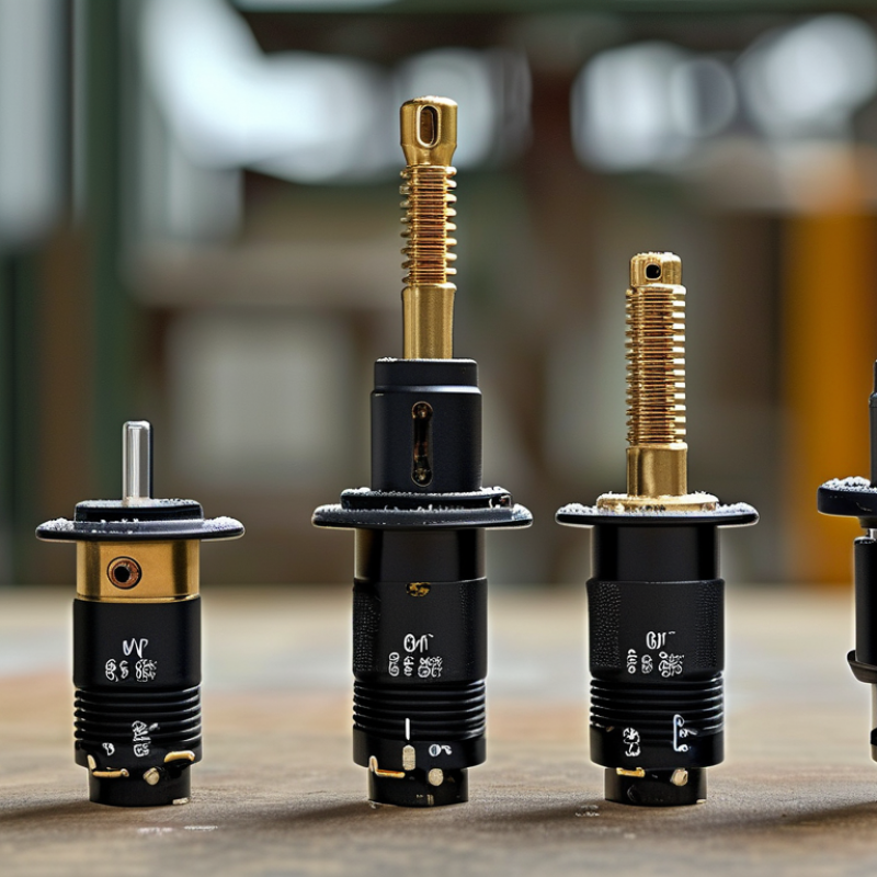
How to Choose Power Supply Connectors?

Identify the Electrical Requirements of the Power Supply

Choosing a power supply connector starts with the electrical requirements, not its shape. Read the equipment label and technical documentation carefully. Confirm the required voltage, current, and whether the input uses AC or DC power. A connector may fit physically while delivering the wrong electrical output. That mistake can damage sensitive circuits.

Check the connector’s voltage and current ratings against the real operating load. Leave a practical safety margin, especially when motors, lamps, or other devices create startup surges. Inspect polarity requirements, because center-positive and center-negative arrangements are not interchangeable. For AC systems, verify frequency and grounding details. For DC systems, confirm the output voltage remains stable under load.

Wire size also matters. Thin conductors can cause voltage drops, heat, and unreliable operation over longer distances. Examine insulation temperature ratings if the connector will sit near a warm enclosure. In field work, I measure the supply with a calibrated multimeter before connecting equipment. I also test the connector under normal load, not only with no load. Small details matter.

Do not rely on appearance alone. Some connectors share identical dimensions but use different pin assignments. I have seen installation errors caused by an overlooked polarity symbol. A second check feels unnecessary until it prevents rework. Record the measured voltage, polarity, and connector pinout before final assembly. These records make later maintenance safer and more consistent.

Match Connector Types with Devices and Power Ratings

Choosing a power supply connector starts with the device, not the cable.
Check the device socket, voltage, current, polarity, and required connector dimensions. A connector can fit and still be wrong. I have seen a loose barrel plug interrupt a device during normal movement. Measure the inner and outer diameters when dimensions are unclear. Small differences can cause heat, unstable contact, or complete failure.

Match the connector type to the device’s power design. Barrel connectors suit many fixed-voltage electronics, while USB-C connectors may support negotiated power levels. Some devices need center-positive polarity; others use a different arrangement. Never assume appearance proves compatibility.

The supply voltage should match the device rating, while its current capacity should meet or exceed the device requirement. A 12-volt device needing 2 amps should not use a 9-volt supply. It also should not rely on a supply rated for only 1 amp. Check the label twice.

Tips:

  • Photograph the original connector before replacement.
  • Record its voltage, current, polarity, and dimensions.
  • Test the connection without forcing it.
  • If the plug feels unusually hot, stop using it.
  • Inspect cable strain, exposed conductors, and insertion depth.
  • I sometimes focus too much on electrical ratings and overlook mechanical stress. That mistake is easy to repeat.
  • Choose a locking or right-angle connector when vibration, tight spaces, or frequent movement could pull the plug sideways.

Check Voltage, Current, Polarity, and Pin Configuration

How to Choose Power Supply Connectors?

A connector can fit and still be electrically wrong. Check the required voltage before comparing shapes or prices. The connector’s rated voltage should exceed the system’s maximum voltage, including startup surges. For current, compare the continuous load with the connector rating, then allow practical headroom. Heat raises contact resistance, especially in compact housings. A 2 A load should not use a 2 A connector without derating. That margin is easy to underestimate.

Polarity deserves a separate check. Confirm positive, negative, and ground positions with the equipment manual and a multimeter. Never trust wire colors alone. Reverse polarity can damage sensitive circuits within seconds. Industry testing guidance under IEC 62368-1 emphasizes safeguards against electrical energy hazards, but the connector choice still requires application-level verification. The standard does not replace measurement.

Pin configuration is equally important. Count every pin, identify keying, and compare the mating side’s view with the wiring side’s view. These diagrams are often mirrored. Check signal pins, shield contacts, and unused terminals. A connector may carry the correct current through one pin but fail when several pins share heat. Grand View Research estimated the global electrical connectors market at about USD 84 billion in 2023, with continued growth through 2030. That scale reflects widespread use, not automatic compatibility. I still recheck polarity after crimping. Small mistakes survive visual inspection. A final continuity and insulation test is worth the extra minute.

How to Choose Power Supply Connectors? — Check Voltage, Current, Polarity, and Pin Configuration
Connector Type Typical Voltage Typical Current Capability Polarity or Power Contacts Common Pin Configuration Key Selection Checks
USB Type-C Power 5 V by default; negotiated levels commonly include 9 V, 12 V, 15 V, and 20 V Up to 3 A without electronically marked cable identification; up to 5 A with a suitable electronically marked cable and compatible equipment Uses defined power and ground contacts rather than a simple fixed center-positive polarity 24 contacts; power contacts are duplicated for reversible insertion. USB Power Delivery uses configuration-channel contacts for negotiation Confirm that the source, cable, and load support the required USB Power Delivery voltage and power level
USB Type-A Power Normally 5 V Commonly 0.5 A for basic USB 2.0 ports, 0.9 A for USB 3.x host ports, and up to 1.5 A for ports supporting battery-charging specifications Fixed power contacts: VBUS and ground; not intended for user-selected polarity 4 contacts: VBUS, D−, D+, and ground Do not assume that every USB-A port can provide the same current; verify the port's charging specification
5.5 mm × 2.1 mm DC Barrel Plug Commonly used in low-voltage DC systems from approximately 5 V to 24 V Often rated around 2 A to 5 A, depending on the exact plug, jack, cable, and temperature conditions Most commonly center-positive, with the outer sleeve negative; center-negative wiring also exists 2 electrical contacts: center pin and outer sleeve Measure the plug dimensions and verify voltage, current rating, and polarity before connection
5.5 mm × 2.5 mm DC Barrel Plug Commonly used in low-voltage DC systems from approximately 5 V to 24 V Often rated around 2 A to 5 A, depending on the specific connector construction and cable assembly Usually center-positive, but polarity must be confirmed from the power-supply label or wiring diagram 2 electrical contacts: center pin and outer sleeve Do not substitute a 2.1 mm and 2.5 mm inner diameter casually; an incorrect fit can cause intermittent contact or damage
2-Pin JST-PH-Style Wire-to-Board Connector Commonly used at extra-low DC voltages, often 3.3 V or 5 V Typically up to approximately 2 A with suitable wire size, contact conditions, and operating temperature Polarity is assigned by the wiring; the connector housing does not inherently guarantee positive and negative orientation 2 pins: positive supply and ground, or another two-wire power arrangement defined by the system Match the housing, contact pitch, keying, and wire order; similar-looking 2-pin connectors may not mate safely
3-Pin Fan-Style Power Connector Commonly 5 V or 12 V, depending on the equipment Often suitable for approximately 0.2 A to 1 A; the exact rating depends on the connector and cable assembly Typically includes a defined positive supply and ground, plus a tachometer or signal contact 3 pins: supply, ground, and speed-sense signal Use only the correct voltage; the signal pin is not an additional power output
4-Pin Fan-Style Power and Control Connector Commonly 12 V for the motor supply Often suitable for approximately 0.2 A to 1 A for typical small loads; check the equipment specification Defined positive supply and ground, with separate control and speed-sense contacts 4 pins: ground, 12 V supply, tachometer signal, and PWM control Do not apply supply voltage to the control or tachometer pins
IEC 60320 C13/C14 AC Power Connector Designed for mains AC; commonly rated up to 250 V AC, subject to the applicable regional approval and cable rating Common ratings include 10 A or 15 A, depending on the regional standard, connector version, and cord set Uses line, neutral, and protective earth; polarity is defined by the inlet and wiring system 3 contacts: line, neutral, and protective earth Verify the local mains voltage, current rating, grounding, insulation, and safety certification
Screw Terminal Block, 2-Position Available for many low-voltage DC applications; the exact voltage rating depends on insulation and spacing Commonly available from approximately 2 A to 15 A or more, depending on pitch, contact design, and wire size Polarity is determined by the wiring; terminals should be clearly marked positive and negative when used for DC power 2 terminals: positive and negative, or line and neutral for an appropriate AC-rated version Confirm pitch, wire range, voltage rating, current rating, and screw-tightening requirements
Safety note: Match the connector's voltage rating to the supply voltage, and select a current rating with adequate margin above the expected load. For DC barrel connectors, verify both the outer diameter and inner pin diameter. Never rely on physical fit alone—check the wiring diagram, polarity symbol, pin numbering, insulation requirements, and the complete connector assembly rating. Mains connectors require appropriate regional safety approvals and installation by a qualified person.

Evaluate Connector Size, Compatibility, and Locking Features

How to Choose Power Supply Connectors?

Connector size should match both available space and electrical load. Measure the housing, cable bend radius, and clearance around the mating area. A larger connector is not automatically safer. It may increase cost, weight, and assembly difficulty. According to Bishop & Associates’ 2024 Global Connector Market report, the worldwide connector market exceeded 80 billion US dollars in 2023. That scale reflects intense demand, but it also shows why careful specification matters. Small errors multiply across high-volume assemblies.

Check compatibility beyond the pin count. Confirm voltage, current, wire gauge, contact material, temperature rating, and mating geometry. IEC 60512 test methods help assess electrical, mechanical, and environmental performance. For cable assemblies, IPC/WHMA-A-620 provides widely used workmanship guidance. I have seen projects pass a basic fit check, then fail after heat cycling. The problem was not the connector size. It was mismatched plating and poor strain relief.

Locking features deserve a practical test. A positive latch should resist vibration but still allow controlled service removal. Threaded, bayonet, and friction-lock designs behave differently under repeated mating. The connector should not loosen when the cable is pulled sideways. Test it with gloves, limited visibility, and realistic installation force. Measure twice. Fit matters. My checklist still needs revision when operators report awkward access, because laboratory confidence does not always reflect field experience.

Verify Safety Standards and Installation Conditions

Choosing a power supply connector starts with safety, not convenience. Check its rated voltage, current, temperature range, and insulation class against actual operating conditions. A connector may pass a catalog check yet fail inside a hot, dusty enclosure. Confirm applicable IEC, UL, or regional requirements. Request test reports from a qualified supplier. Do not trust a printed mark alone. Verify its certificate number and scope.

Installation conditions deserve equal attention. Measure available space, cable bend radius, vibration, moisture, condensation, and expected mating cycles. Use the specified wire size, stripping length, crimp tool, and torque. Poor crimping creates resistance and heat. Sometimes, a faint burnt smell appears first. Ensure protective earth paths remain continuous. Keep exposed contacts away from metal surfaces. Check locking features and strain relief by hand after assembly.

In field work, I once called a connector secure because it clicked. That was not enough. The cable later pulled against the terminal. A continuity test, insulation check, and gentle pull test would have exposed the weakness. I now review installation drawings twice, although small assumptions still escape notice. If conditions change, recalculate the load and recheck clearances. Record the test results beside the finished assembly.

How to Choose Power Supply Connectors?

Verify safety standards and installation conditions before selecting a connector.

How to read the chart

The first IP characteristic is based on IEC 60529 and indicates protection against access to hazardous parts and solid foreign objects. The values shown are the maximum object or probe diameter associated with IP1X through IP4X. A smaller diameter indicates stronger protection against solid-object access.

For a complete power connector selection, also verify the second IP characteristic for water protection, rated voltage and current, insulation requirements, temperature range, cable size, pollution level, mechanical locking, and the installation environment. The connector assembly must be installed according to the applicable product and electrical safety requirements.